BrickPickNPlace
Feb 2026 to Jun 2026
The perception node for a UR3e that builds LEGO figures: it finds and classifies the bricks on the table, and works out where on the plate the next one can legally go.
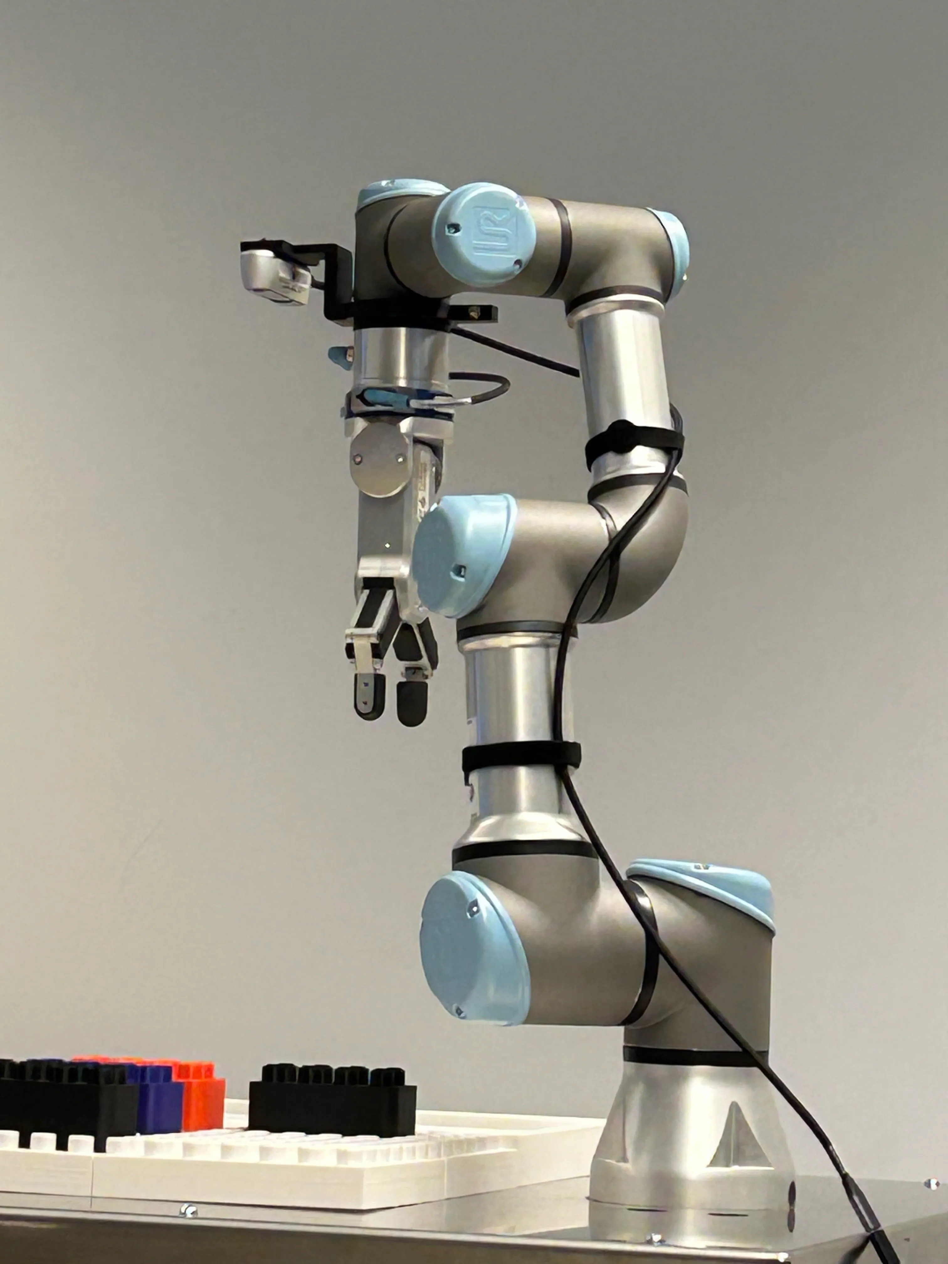
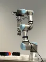
The rig the node runs on. The camera is fixed above the wrist and everything it publishes goes out in the camera optical frame, so the interaction node is the one that transforms into the robot base frame. 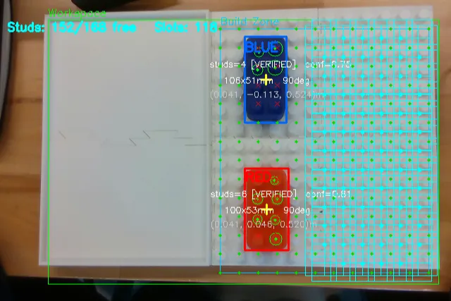
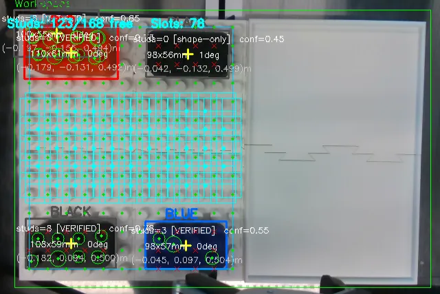
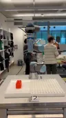
An early frame taken before the camera went onto the arm. Both bricks are verified, and the grid reports 152 of 168 studs free with 118 legal slots left to place into. The full system running, with the arm working through a figure a brick at a time. The first iteration, recorded before the work zone corners and the plate corners had been set. The node finds the bricks on the table, but with no calibrated grid behind it there is nowhere yet to say they can go. 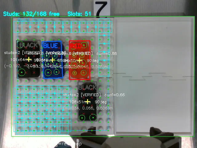
A second arrangement, and the case where the confidence score earns its keep. The black bricks are still found and classified correctly, but HoughCircles clears only two of the eight studs on them: printed black PLA under that lighting gives the circle detector almost nothing to lock onto, so they come through verified at a visibly lower score than the red and blue beside them.


1 / 6
The Problem
Robotics Studio 2 set the task: a UR3e fitted with a parallel-jaw gripper picks LEGO bricks off a table and assembles a requested figure on a base plate, sorting them by colour or by size. The pattern is chosen from a desktop interface or spoken aloud, and the arm works through it a brick at a time.
Perception has to answer two questions, and only one of them is object detection. The first is what is on the table: which bricks, what colour, what size, and where each one sits in three dimensions. The second is harder and less obvious. Given the plate as it currently stands, where can the next brick legally go? A pick is worth nothing if the arm has nowhere valid to put the piece, so the node has to reason about the plate as a grid of occupied and free positions, not just recognise objects.
My Role
A team of four. I was solely responsible for the perception and mapping node and the calibration it depends on. The other three owned motion planning through MoveIt Task Constructor, the interaction state machine and its interface, and the voice control.
Technical Approach
Detection starts with HSV segmentation into colour masks, one per supported colour. White is deliberately absent from those ranges, because the work surface is white and including it would turn the table itself into a candidate. Contours from each mask are then validated against a table of known brick variants on two independent measures, aspect ratio and real-world size, so a 4 by 2 brick at 100 by 50 millimetres is distinguished from a 3 by 2 at 75 by 50 rather than both passing as generic rectangles.
Anything that survives that gets checked for studs. HoughCircles looks inside the candidate for the circles a real brick would show, expecting about eight of them at the known 25 millimetre pitch. The two tests then combine into a single confidence: shape agreement contributes up to 0.65, reduced by how far the aspect ratio and size are from the variant it matched, and stud verification adds up to 0.35 scaled by how many of the eight studs were actually found. A rectangle of the right size and colour with no studs on it never reaches a usable score, which is the point.
Pose comes from the contour moments and the oriented bounding box, with yaw taken from the box angle. Depth is the median of a 21 by 21 pixel window rather than a single reading, because the D435i is noisy enough that one pixel is not worth trusting.
The build-zone half works on a grid instead. The plate is 12 columns by 14 rows, 168 studs at a 25 millimetre pitch, interpolated between two corners fixed during calibration. Each detected brick’s oriented box is tested against every stud position to mark it occupied, and then a 4 by 2 window slides across the grid in both orientations. A slot counts as legal only when its own eight studs are free and the single-stud ring around it is free too, or falls outside the plate. That ring is what stops the gripper fouling a brick already placed next to the target.
The node publishes on a trigger rather than streaming. It waits for an empty message, captures five frames, and publishes the best of them, so the arm acts on one settled picture of the table instead of chasing a feed that changes underneath it. Those results are latched, which means a node that subscribes late still receives the most recent snapshot straight away rather than blocking until the next trigger. Everything goes out in the camera optical frame, and the interaction node transforms it into the robot base frame.
Calibration is two interactive steps, saved to disk so it survives a restart. Drag a rectangle around the working area to set the region of interest and sample the surface depth inside it, then click the top-left and bottom-right stud centres of the plate, from which all 168 stud positions are interpolated.
Outcome and What I Would Do Differently
The node did everything it was specified to do, running as part of the full system rather than on its own. Calibration held once it was set. Bricks came out with the right colour and size variant, and with a three dimensional pose the motion side could transform into the robot frame and act on directly. The plate analysis reported occupied and free studs correctly and produced legal placement slots for the interaction node to choose from.
The boundaries are in the calibration and the slot search, and they are constraints I set rather than faults I found later. Registering the grid from two clicked corners assumes the plate is square to the camera, so an oblique plate has to be physically straightened rather than corrected in software. Taking four corners and solving a perspective transform would remove that, and would also help the related case where stud verification degrades past roughly thirty degrees of obliquity, because studs project as ellipses and the circle detector stops finding them. The slot search only ever looks for 4 by 2 footprints, so a plate holding mixed brick sizes cannot be planned properly until that window generalises to the variant table the detector already carries. That is the first thing I would build next.