Danish Silva

Final year Mechatronics Engineering student at UTS, taking hardware from schematic and PCB design through power, sensing and control to a tested working system.

About Me

Hi, I’m Danish.

I’m in my final year of Mechatronics Engineering at UTS, heading for robotics. The work I like best sits where the electronics, the firmware and the mechanical side all have to agree with each other, which is usually where things go wrong and usually where they get interesting.

Hardware is what I’m most confident in. I’m comfortable starting at a blank schematic and going the whole way through, power, sensing, control, board layout, to something on a bench doing what it was meant to do. I can take a mechanical design from a rough idea to drawings someone could actually make parts from, and I’ve been steadily pulling computer vision into the mix as I get further into robotics.

The other half of it is people. This year I led a seven person team building a compliance test rig for an industrial client, from a brief to a working, documented rig. I got a lot out of the engineering. I got more out of learning how to run it.

Right now I’m pushing further into robotics and vision, and I’m after a graduate role close to hardware.

Have a look at my projects below, and feel free to get in touch.

Experience

Engineering Intern and Team Lead

May 2026 to Aug 2026

Optik Consultancy, Client: Sensear

Botany, NSW

Led a seven member engineering team building an in-house EN 352 compliance testing system for Sensear’s industrial earmuff headsets, replacing costly external lab testing, while owning project direction, task allocation and client engineering communication.

Designed the test system electronics end to end, including ESP32-based control, a high-torque servo drive for headband fatigue cycling, and a multi-rail power supply with buck and linear regulation plus reverse-polarity, over-current and over-voltage protection.

Engineered the headband force measurement front end, using a Wheatstone bridge load cell with a 24-bit ADC, differential filtering and ratiometric excitation, for repeatable clamp force measurement to EN 13819-1.

Delivered full system schematics, a custom ESP32-S3 PCB and a costed bill of materials, and specified the acoustic measurement chain (loudspeaker array and audio interface) for attenuation testing per ISO 4869.

  • Team Leadership
  • Power Electronics
  • Sensor Front End
  • PCB Design
  • Compliance Testing

Marketing Coordinator

Mar 2022 to Jun 2024

LRS Australia

North Sydney, NSW

Coordinated design, logistics and on-site operations across three or more national expos with internal teams and external vendors, increasing customer leads.

Diagnosed and resolved hardware and software faults through systematic testing, maintaining customer satisfaction above 90 percent, and designed a three step dispatch verification checklist that reduced shipping errors.

Liaised with customers, printers and vendors to deliver high quality outcomes under tight deadlines, strengthening communication, stakeholder management and adaptability.

  • Stakeholder Management
  • Client Communication
  • Event Operations
  • Fault Diagnosis

Projects

MEMS-Based Step Tracker

Feb 2026 to Jun 2026

A wrist-worn step tracker built end to end: a custom ESP32 shield sized to the dev board it plugs into, and the firmware that turns three analogue axes into a step count.

  • Embedded
  • PCB

The Problem

Embedded Mechatronics Studio set the brief: build a step tracker around an ADXL335 accelerometer. The unit suggested an Arduino as the microcontroller. I used an ESP32 instead and designed a shield that plugs straight onto the dev board, because the smaller assembly is the only version of this that makes sense worn on a wrist.

That decision set the real constraint. The shield had to stay inside the outline of the ESP32 dev board while carrying a complete power supply, three analogue filter channels, the accelerometer connector and the remaining peripherals. Almost every layout decision after that came out of the area budget.

My Role

A team project. I owned the power supply design and picked up the analogue filter design as well when that work stalled. All of the PCB routing was mine, along with the board file itself, the assembly and soldering of the finished unit, and the firmware it runs.

Technical Approach

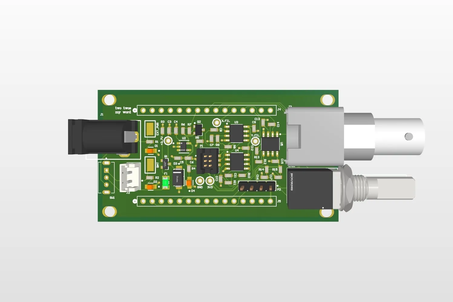
Power arrives from either a barrel jack or a lithium polymer cell, and passes three protection stages before it reaches anything that matters. A resettable polyfuse opens if the load draws more than 500 mA. A P-channel MOSFET blocks reverse polarity, chosen over a series diode because it wastes far less voltage in normal operation. A TVS diode clamps anything above five volts, which is what a bench supply transient tends to look like. Only then does the regulator, an AP2112K, take the input down to a 3.3V rail. I modelled the regulator and the protection in LTspice before committing to fabrication, checking the current the board would actually draw and confirming each stage tripped where I had designed it to rather than somewhere near it. Five test points sit on the board for the same reason: so the rails can be probed instead of assumed.

The ADXL335 puts out three analogue channels, one per axis, so the front end is three identical conditioning chains. Each opens with a unity gain buffer, which presents a high impedance to the accelerometer so the sensor’s own output resistance cannot drag the filter’s corner frequency around with it, and follows with a second order Sallen-Key low pass tuned as a Butterworth for a flat passband and a steeper roll off than a single RC stage could manage. With 6.8k resistors and 680 nF and 330 nF capacitors the corner lands at 50.4 Hz and the Q at 0.718, near enough to the 0.707 a Butterworth asks for. That leaves the one to three hertz of a walking step completely untouched while keeping the noise above it out.

The rest of the board was integration. Subsystems came from different people, so the schematic had to reconcile them: separating the power domains so the supply and analogue sections did not share a return path, keeping the filter traces short and away from noisy nets, and placing every component so the whole thing still fitted the dev board outline.

The firmware is C++ on the Arduino framework, built with PlatformIO. Rather than trusting any single axis it works from the magnitude of the acceleration vector, so the reading holds up when the wrist rotates. Gravity is removed with an exponential moving average, which tracks the slowly varying component and leaves the movement behind, and the result is smoothed before detection. A step is a peak above a threshold with hysteresis, so one step cannot be counted twice while the signal wobbles around the trigger point, and the timing between peaks gives a cadence, which is what separates idle from walking from running.

Calibration runs on the device rather than being baked in. It walks the user through holding each axis at plus and minus one g, then derives that axis’s zero point and sensitivity from the two readings, which is what makes the magnitude figure trustworthy from one board to the next. The menu runs on an OLED driven over I2C with a rotary encoder for input, and both are peripherals the shield had to find room for inside the same outline.

Outcome and What I Would Do Differently

The board was fabricated, assembled and worked as designed, and the project was graded a High Distinction. The protection behaved on the bench the way LTspice said it would, and the measured filter gain and 50 Hz corner matched the values I had calculated.

The mistake worth recording is in the pin assignment. I chose the ESP32 for its Wi-Fi, intending to serve a small phone app showing a live step count. I routed the filter outputs into ADC2, and on the ESP32 the Wi-Fi radio claims ADC2 for itself, so those channels cannot be read while the radio is running. Counting steps and serving the app at the same time was impossible on the board as built. Moving the three channels to ADC1 would have cost nothing at design time. I now check what a peripheral shares silicon with before assigning a pin, rather than after.

Tech Stack

  • Altium Designer
  • LTspice
  • C++
  • PlatformIO
  • ESP32
  • ADXL335
  • Altium 365

BrickPickNPlace

Feb 2026 to Jun 2026

The perception node for a UR3e that builds LEGO figures: it finds and classifies the bricks on the table, and works out where on the plate the next one can legally go.

  • Robotics

The Problem

Robotics Studio 2 set the task: a UR3e fitted with a parallel-jaw gripper picks LEGO bricks off a table and assembles a requested figure on a base plate, sorting them by colour or by size. The pattern is chosen from a desktop interface or spoken aloud, and the arm works through it a brick at a time.

Perception has to answer two questions, and only one of them is object detection. The first is what is on the table: which bricks, what colour, what size, and where each one sits in three dimensions. The second is harder and less obvious. Given the plate as it currently stands, where can the next brick legally go? A pick is worth nothing if the arm has nowhere valid to put the piece, so the node has to reason about the plate as a grid of occupied and free positions, not just recognise objects.

My Role

A team of four. I was solely responsible for the perception and mapping node and the calibration it depends on. The other three owned motion planning through MoveIt Task Constructor, the interaction state machine and its interface, and the voice control.

Technical Approach

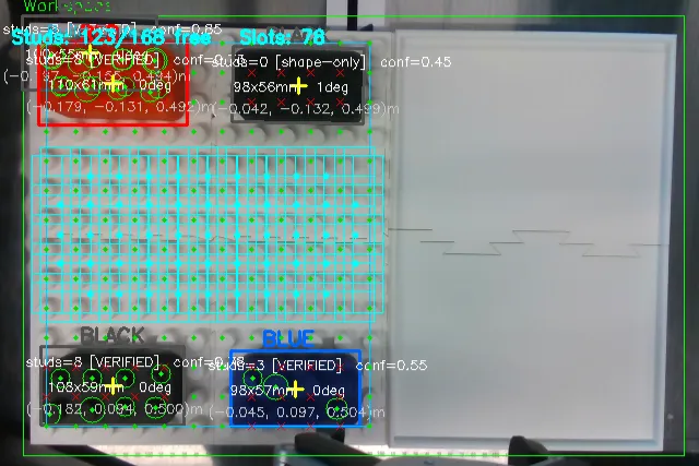
Detection starts with HSV segmentation into colour masks, one per supported colour. White is deliberately absent from those ranges, because the work surface is white and including it would turn the table itself into a candidate. Contours from each mask are then validated against a table of known brick variants on two independent measures, aspect ratio and real-world size, so a 4 by 2 brick at 100 by 50 millimetres is distinguished from a 3 by 2 at 75 by 50 rather than both passing as generic rectangles.

Anything that survives that gets checked for studs. HoughCircles looks inside the candidate for the circles a real brick would show, expecting about eight of them at the known 25 millimetre pitch. The two tests then combine into a single confidence: shape agreement contributes up to 0.65, reduced by how far the aspect ratio and size are from the variant it matched, and stud verification adds up to 0.35 scaled by how many of the eight studs were actually found. A rectangle of the right size and colour with no studs on it never reaches a usable score, which is the point.

Pose comes from the contour moments and the oriented bounding box, with yaw taken from the box angle. Depth is the median of a 21 by 21 pixel window rather than a single reading, because the D435i is noisy enough that one pixel is not worth trusting.

The build-zone half works on a grid instead. The plate is 12 columns by 14 rows, 168 studs at a 25 millimetre pitch, interpolated between two corners fixed during calibration. Each detected brick’s oriented box is tested against every stud position to mark it occupied, and then a 4 by 2 window slides across the grid in both orientations. A slot counts as legal only when its own eight studs are free and the single-stud ring around it is free too, or falls outside the plate. That ring is what stops the gripper fouling a brick already placed next to the target.

The node publishes on a trigger rather than streaming. It waits for an empty message, captures five frames, and publishes the best of them, so the arm acts on one settled picture of the table instead of chasing a feed that changes underneath it. Those results are latched, which means a node that subscribes late still receives the most recent snapshot straight away rather than blocking until the next trigger. Everything goes out in the camera optical frame, and the interaction node transforms it into the robot base frame.

Calibration is two interactive steps, saved to disk so it survives a restart. Drag a rectangle around the working area to set the region of interest and sample the surface depth inside it, then click the top-left and bottom-right stud centres of the plate, from which all 168 stud positions are interpolated.

Outcome and What I Would Do Differently

The node did everything it was specified to do, running as part of the full system rather than on its own. Calibration held once it was set. Bricks came out with the right colour and size variant, and with a three dimensional pose the motion side could transform into the robot frame and act on directly. The plate analysis reported occupied and free studs correctly and produced legal placement slots for the interaction node to choose from.

The boundaries are in the calibration and the slot search, and they are constraints I set rather than faults I found later. Registering the grid from two clicked corners assumes the plate is square to the camera, so an oblique plate has to be physically straightened rather than corrected in software. Taking four corners and solving a perspective transform would remove that, and would also help the related case where stud verification degrades past roughly thirty degrees of obliquity, because studs project as ellipses and the circle detector stops finding them. The slot search only ever looks for 4 by 2 footprints, so a plate holding mixed brick sizes cannot be planned properly until that window generalises to the variant table the detector already carries. That is the first thing I would build next.
Tech Stack

  • Python
  • ROS 2 Humble
  • OpenCV
  • pyrealsense2
  • NumPy
  • Intel RealSense D435i
  • Universal Robots UR3e

Pitwall

Apr 2026 to May 2026

An F1 inspired racing agent that learns to trade lap time against tyre life, pairing a driving policy with a learned wear model to work out when a pit stop pays for itself.

  • Machine Learning

The Problem

Driving a car around a track is a solved demonstration in reinforcement learning. Built for AI in Robotics at UTS, Pitwall makes the task an economic one instead. The agent runs a multi-lap race on a wrapped CarRacing environment where the tyres degrade as it drives, and a pit stop resets them at a cost. Going faster wears the tyres sooner. Stopping costs time now to save time later. The agent has to decide when that trade is worth taking.

That means two learned systems in one loop rather than one. A policy that drives, and a separate model that predicts how quickly the tyres are wearing, feeding the state the policy sees.

My Role

A team of four for the subject. I owned the system architecture and the reinforcement learning agent. The environment wrapper, the tyre degradation model and the evaluation harness were owned by the other three, and the documentation site credits each of them.

The architecture decision that mattered was keeping those four pieces loosely coupled behind narrow, typed interfaces. Four people were changing code at once, and a driving policy is slow to retrain, so the model, the environment and the analysis had to be able to move without dragging the agent behind them.

Technical Approach

The agent is proximal policy optimisation through Stable Baselines3, on a dictionary observation rather than pixels alone. It sees a 96 by 96 camera frame, stacked four deep so motion is visible in a single observation, alongside a three element vector carrying tyre wear, the current lap and the compound fitted. That vector is the part that makes the strategy learnable: wear does not appear in the image, so without it the policy has no way to know a stop is coming due. Actions are continuous steering, throttle and brake, and training runs across eight parallel environments.

Wear comes from a gradient boosting regressor, 300 trees at depth four, trained on 12,000 synthetic samples of stylised F1 physics. It predicts a per-step wear rate from speed, cornering load, lap number, current wear and compound, so wear responds to how the car is being driven rather than ticking down on a timer.

Training runs in two phases. The first spends 1.5 million steps on a single fixed track so the agent learns to drive one sequence of corners without also fighting a new layout every episode. The second resumes from that checkpoint and trains three million more on random tracks. Splitting it that way cuts the variance early, at the price of a real dip in performance when the fixed track is taken away.

Outcome and What I Would Do Differently

The result that taught me most was a failure. Partway through, the agent found a local optimum where it simply span on the spot: it stayed on the track, took the small per-step penalty, and never completed a lap. The aggregate numbers did not show it. Mean reward looked stable and episode length looked healthy, because surviving without progressing is indistinguishable from surviving while progressing if you only watch the totals. It was obvious within seconds of actually watching an episode.

The fix was the reward, not the network. A bonus for completing a lap gave the policy a terminal goal to aim at, a stagnation rule ended episodes that went 300 steps without reaching new track, and the hard off-track barrier became a soft per-step penalty so leaving the track was expensive rather than fatal. Behaviour changed qualitatively after that: standing still stopped paying.

Two things I would do differently. I would build the visualisation before the agent, not after; the racing line plot that exposed the problem took an afternoon and would have saved days had it existed from the start. And I would exhaust the reward function before touching the architecture. A bigger network only reaches the wrong objective faster.

Tech Stack

  • Python
  • Stable Baselines3
  • Gymnasium
  • scikit-learn
  • Box2D
  • TensorBoard

FireRed RL Agent

Apr 2026 to May 2026

A reinforcement learning agent that plays Pokémon FireRed from pixels, with the reward read out of the game's memory rather than off the screen.

  • Machine Learning

The Problem

This one came after Pitwall, as a personal project, to try reinforcement learning somewhere the reward is not handed to you. CarRacing pays the agent for progress on almost every frame. A role-playing game pays it for almost nothing across hours of play, and the target here, beating the first gym leader, sits a long way behind a wall of walking, talking and levelling that carries no obvious score at all.

So the interesting question is not which algorithm to use. It is what to reward. Nothing on screen reliably tells you whether the last thousand frames were progress or a corridor walked twice, which means reading the picture is the wrong instrument for the job.

My Role

Solo. Environment, reward design, training setup and monitoring.

Technical Approach

The agent is PPO through Stable Baselines3 with a NatureCNN over the frames, which come in as 84 by 84 greyscale, stacked three deep so motion is visible, with 24 frames skipped between decisions because a game running at sixty frames a second does not need sixty decisions a second. Actions are eight discrete buttons. The emulator is stable-retro on the libretro mGBA core, run headless, twelve processes in parallel. The repository takes no game with it; it imports a ROM the user already owns.

The reward is where the actual design sits, and it comes from parsing the game’s memory rather than the screen. Exploration is scored on the map identifier and the coordinates within it, so entering somewhere genuinely new pays and pacing a corridor does not, with a hash of the frame as a fallback for places the coordinates alone cannot separate. Party level pays out on a square root curve, so early progress is worth more than grinding the same patch of grass indefinitely, and only counts increases, which stops the agent farming a level it lost and regained. Badges pay a bonus, health changes during battle give a dense signal in the fights that matter, and a small per-step cost discourages standing still.

Every component is logged separately to TensorBoard rather than only as a total, alongside unique tiles seen and distinct maps reached. A single reward curve tells you something is working; the breakdown tells you which part.

Outcome and What I Would Do Differently

It did not beat Brock, and it was never going to on the hardware I had. A full run is fifty million steps across twelve emulators, which is a job shaped for rented compute rather than a desktop that also has to be a desktop. What the training I could run did establish is that the machinery works: the environment steps correctly, the reward components fire when they should, and the monitoring showed exploration widening and levels climbing as the agent played rather than sitting flat. The design was sound and the budget was not.

Knowing that, I would attack the compute rather than the code. Renting GPU time for a single long run is the direct answer. The cheaper one is to make the problem smaller before spending anything on it: start training from a save state near the gym instead of from the title screen, so the agent is not made to rediscover the first hour of the game every episode, and cut the action space to the buttons that matter in that stretch. That is the same idea I would reach for in any long-horizon task, and it is worth building before the training budget, not after.

Tech Stack

  • Python
  • PyTorch
  • Stable Baselines3
  • stable-retro
  • Gymnasium
  • TensorBoard
  • CUDA

UR3e RealSense Visual Servoing

Aug 2025 to Nov 2025

Eye-in-hand visual servoing that keeps a UR3e arm locked onto a moving checkerboard, closing the control loop in image space at 15 to 20 Hz.

  • Robotics
  • Controls

The Problem

Sensors and Control for Mechatronic Systems set the brief: make a UR3e arm follow a checkerboard using an Intel RealSense camera mounted on the tool. The board is moved by hand, so the arm has to react continuously rather than execute a path planned in advance.

Image based visual servoing closes the loop in the image itself. Instead of estimating where the target sits in three dimensions and then planning a motion to reach it, the controller works directly on the difference between where the feature points appear and where they should appear. That tolerates calibration error well. A small mistake in the tool to camera transform shows up as a slightly wrong velocity that the next frame corrects, rather than a wrong goal pose the robot drives confidently towards.

My Role

This ran as a team project for the subject, though most of the implementation was mine. I wrote both halves of the running system: the vision process that finds the board and turns it into a camera velocity, and the robot process that converts that velocity into joint motion and streams it to the arm. Tuning the controller gain and the velocity limits until the motion settled was also mine.

Technical Approach

The system runs as two processes that talk over a TCP socket.

The vision process detects a 6 by 5 checkerboard in the RealSense colour stream with OpenCV and takes depth for the target from the aligned depth stream. It compares the detected corner positions against their desired positions in the image, builds the interaction matrix that relates image space motion to camera motion, and solves it for a six element camera velocity. That vector is what goes across the socket, so the vision side never needs to know anything about the robot.

The robot process converts camera velocity into joint velocity. It applies the tool to camera transform to move the velocity into the robot’s frame, then multiplies by the pseudoinverse of the UR3e Jacobian to get joint rates. Those become micro-step joint trajectories published to the arm through rosbridge at 15 to 20 Hz. Controller gain and per joint velocity limits are the two things that decide whether the result is responsive or unstable, and both were tuned by hand against the real arm.

Outcome and What I Would Do Differently

The system worked. The arm tracked the board and held alignment as it was moved around by hand.

Two limitations were clear by the end. The Jacobian solution was not always smooth, and near certain configurations the translation came out jumpy rather than continuous. The usable field of view was also narrower than expected, so the board had to be held close to the camera before detection was reliable, which limited how far the arm could be led.

The change I would make first is the transport. The TCP socket between the two processes exists because the work was done on Windows. Running on Ubuntu and letting ROS carry the messages end to end would remove the custom protocol and the extra hop, leaving one system to reason about instead of two halves joined by a socket. I would also look at damping the Jacobian solution near singular configurations, since that is the most likely cause of the jumpy translation.

Tech Stack

  • Python
  • OpenCV
  • ROS
  • rosbridge
  • pyrealsense2
  • Intel RealSense D435
  • Universal Robots UR3e

What I Work With

Let's Connect

I'm graduating in 2027 and looking for a graduate role where I can keep working close to hardware. If you're hiring, or just want to talk about something you're building, I'd love to hear from you.

Start a Conversation

hello@danishsilva.com