MEMS-Based Step Tracker
Feb 2026 to Jun 2026
A wrist-worn step tracker built end to end: a custom ESP32 shield sized to the dev board it plugs into, and the firmware that turns three analogue axes into a step count.
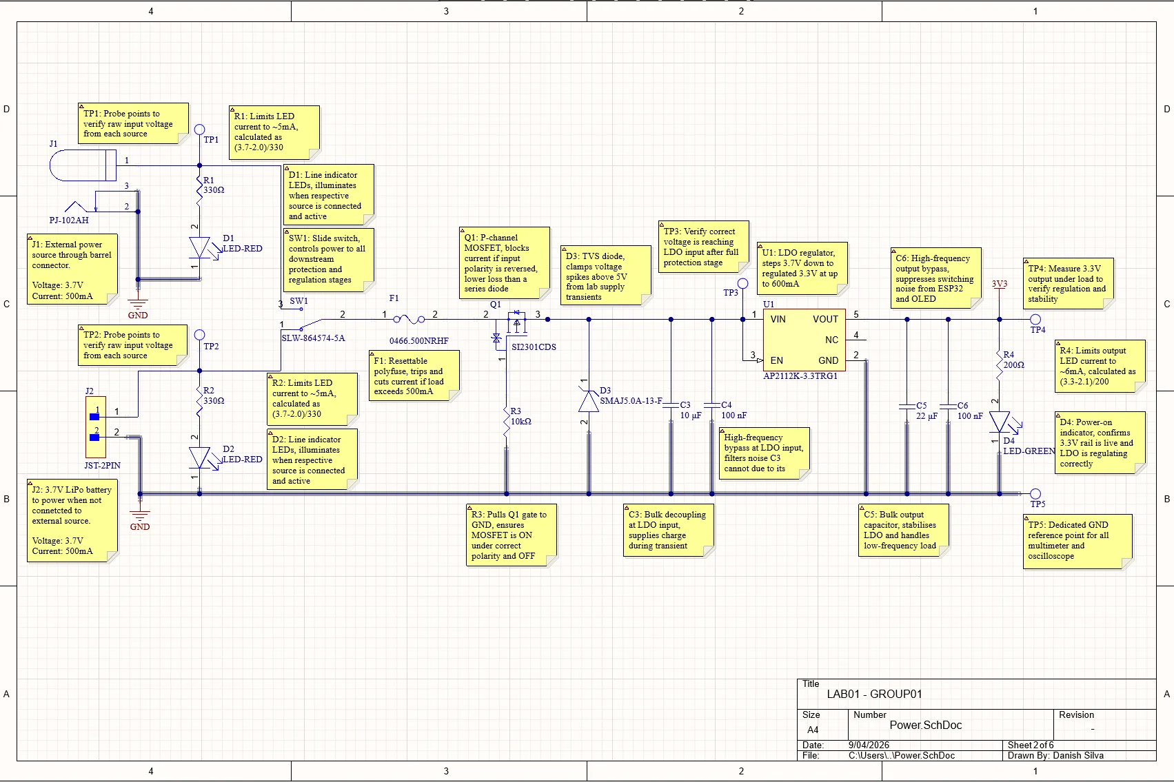
The supply, annotated. Three protection stages sit ahead of the regulator, and five test points let the rails be probed rather than assumed. 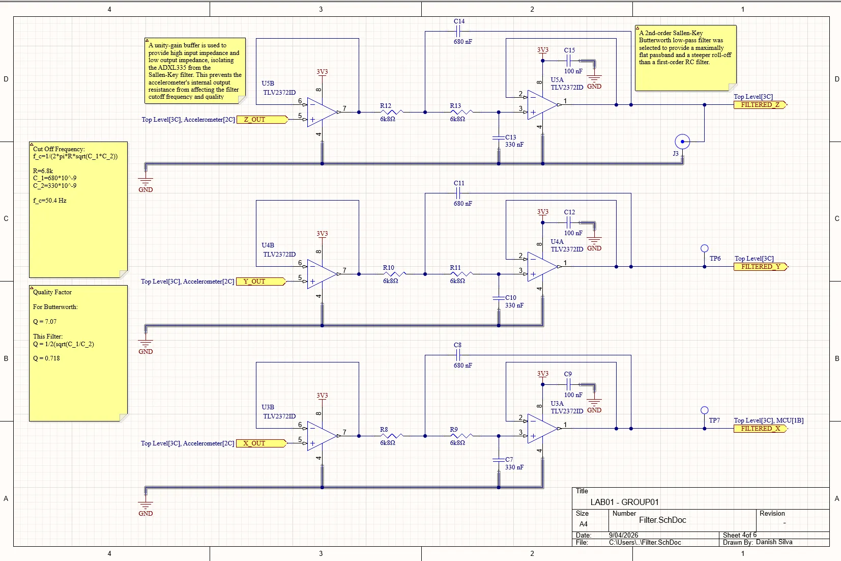
One conditioning chain per accelerometer axis, buffered so the sensor cannot pull the filter corner around. 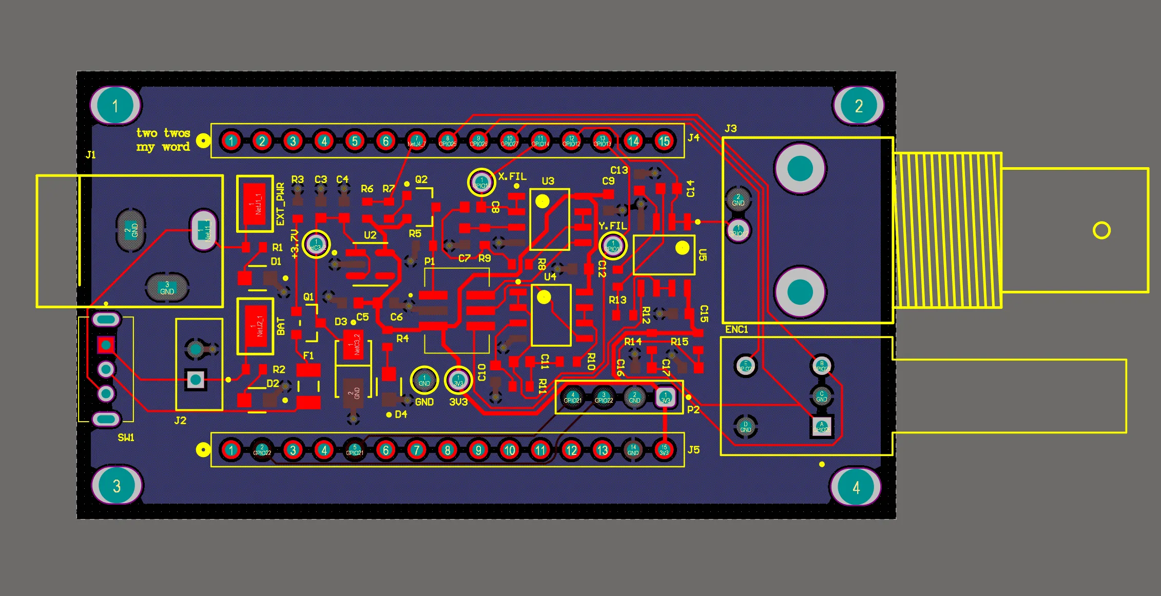
The routing, kept inside the dev board outline with the analogue section held away from the supply. 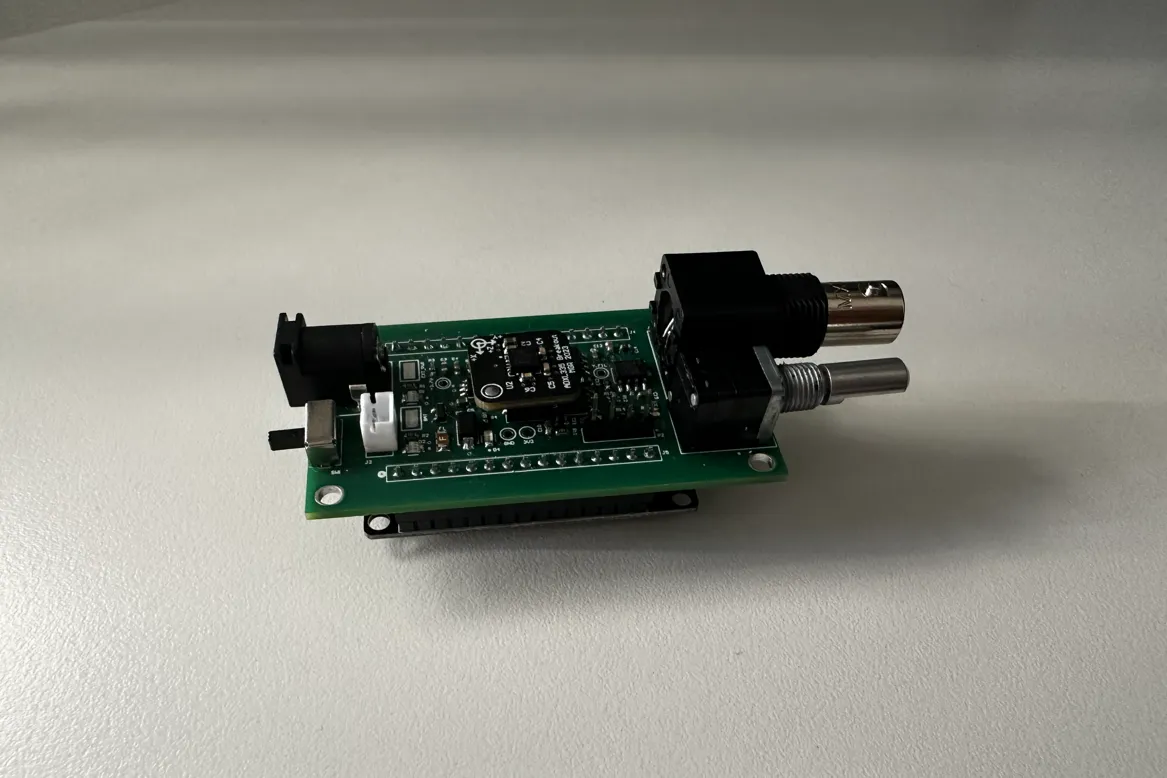
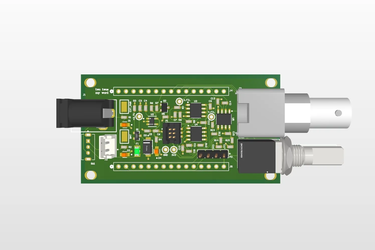
Assembled and seated on the board it was sized around. 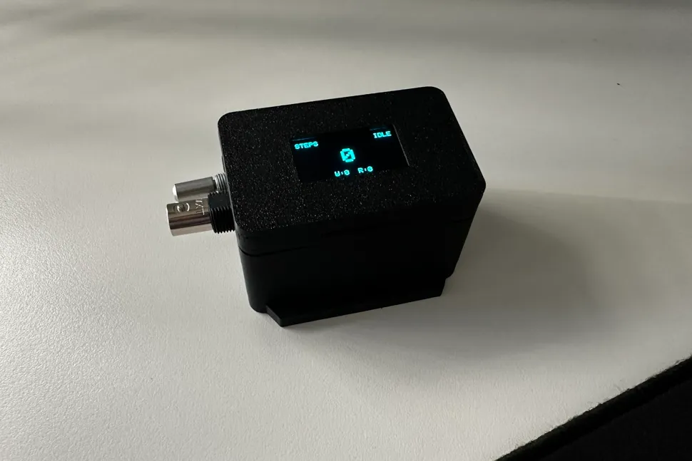
Running in its enclosure, with the step count and the idle, walking and running state on the display.

1 / 6
The Problem
Embedded Mechatronics Studio set the brief: build a step tracker around an ADXL335 accelerometer. The unit suggested an Arduino as the microcontroller. I used an ESP32 instead and designed a shield that plugs straight onto the dev board, because the smaller assembly is the only version of this that makes sense worn on a wrist.
That decision set the real constraint. The shield had to stay inside the outline of the ESP32 dev board while carrying a complete power supply, three analogue filter channels, the accelerometer connector and the remaining peripherals. Almost every layout decision after that came out of the area budget.
My Role
A team project. I owned the power supply design and picked up the analogue filter design as well when that work stalled. All of the PCB routing was mine, along with the board file itself, the assembly and soldering of the finished unit, and the firmware it runs.
Technical Approach
Power arrives from either a barrel jack or a lithium polymer cell, and passes three protection stages before it reaches anything that matters. A resettable polyfuse opens if the load draws more than 500 mA. A P-channel MOSFET blocks reverse polarity, chosen over a series diode because it wastes far less voltage in normal operation. A TVS diode clamps anything above five volts, which is what a bench supply transient tends to look like. Only then does the regulator, an AP2112K, take the input down to a 3.3V rail. I modelled the regulator and the protection in LTspice before committing to fabrication, checking the current the board would actually draw and confirming each stage tripped where I had designed it to rather than somewhere near it. Five test points sit on the board for the same reason: so the rails can be probed instead of assumed.
The ADXL335 puts out three analogue channels, one per axis, so the front end is three identical conditioning chains. Each opens with a unity gain buffer, which presents a high impedance to the accelerometer so the sensor’s own output resistance cannot drag the filter’s corner frequency around with it, and follows with a second order Sallen-Key low pass tuned as a Butterworth for a flat passband and a steeper roll off than a single RC stage could manage. With 6.8k resistors and 680 nF and 330 nF capacitors the corner lands at 50.4 Hz and the Q at 0.718, near enough to the 0.707 a Butterworth asks for. That leaves the one to three hertz of a walking step completely untouched while keeping the noise above it out.
The rest of the board was integration. Subsystems came from different people, so the schematic had to reconcile them: separating the power domains so the supply and analogue sections did not share a return path, keeping the filter traces short and away from noisy nets, and placing every component so the whole thing still fitted the dev board outline.
The firmware is C++ on the Arduino framework, built with PlatformIO. Rather than trusting any single axis it works from the magnitude of the acceleration vector, so the reading holds up when the wrist rotates. Gravity is removed with an exponential moving average, which tracks the slowly varying component and leaves the movement behind, and the result is smoothed before detection. A step is a peak above a threshold with hysteresis, so one step cannot be counted twice while the signal wobbles around the trigger point, and the timing between peaks gives a cadence, which is what separates idle from walking from running.
Calibration runs on the device rather than being baked in. It walks the user through holding each axis at plus and minus one g, then derives that axis’s zero point and sensitivity from the two readings, which is what makes the magnitude figure trustworthy from one board to the next. The menu runs on an OLED driven over I2C with a rotary encoder for input, and both are peripherals the shield had to find room for inside the same outline.
Outcome and What I Would Do Differently
The board was fabricated, assembled and worked as designed, and the project was graded a High Distinction. The protection behaved on the bench the way LTspice said it would, and the measured filter gain and 50 Hz corner matched the values I had calculated.
The mistake worth recording is in the pin assignment. I chose the ESP32 for its Wi-Fi, intending to serve a small phone app showing a live step count. I routed the filter outputs into ADC2, and on the ESP32 the Wi-Fi radio claims ADC2 for itself, so those channels cannot be read while the radio is running. Counting steps and serving the app at the same time was impossible on the board as built. Moving the three channels to ADC1 would have cost nothing at design time. I now check what a peripheral shares silicon with before assigning a pin, rather than after.