UR3e RealSense Visual Servoing
Aug 2025 to Nov 2025
Eye-in-hand visual servoing that keeps a UR3e arm locked onto a moving checkerboard, closing the control loop in image space at 15 to 20 Hz.
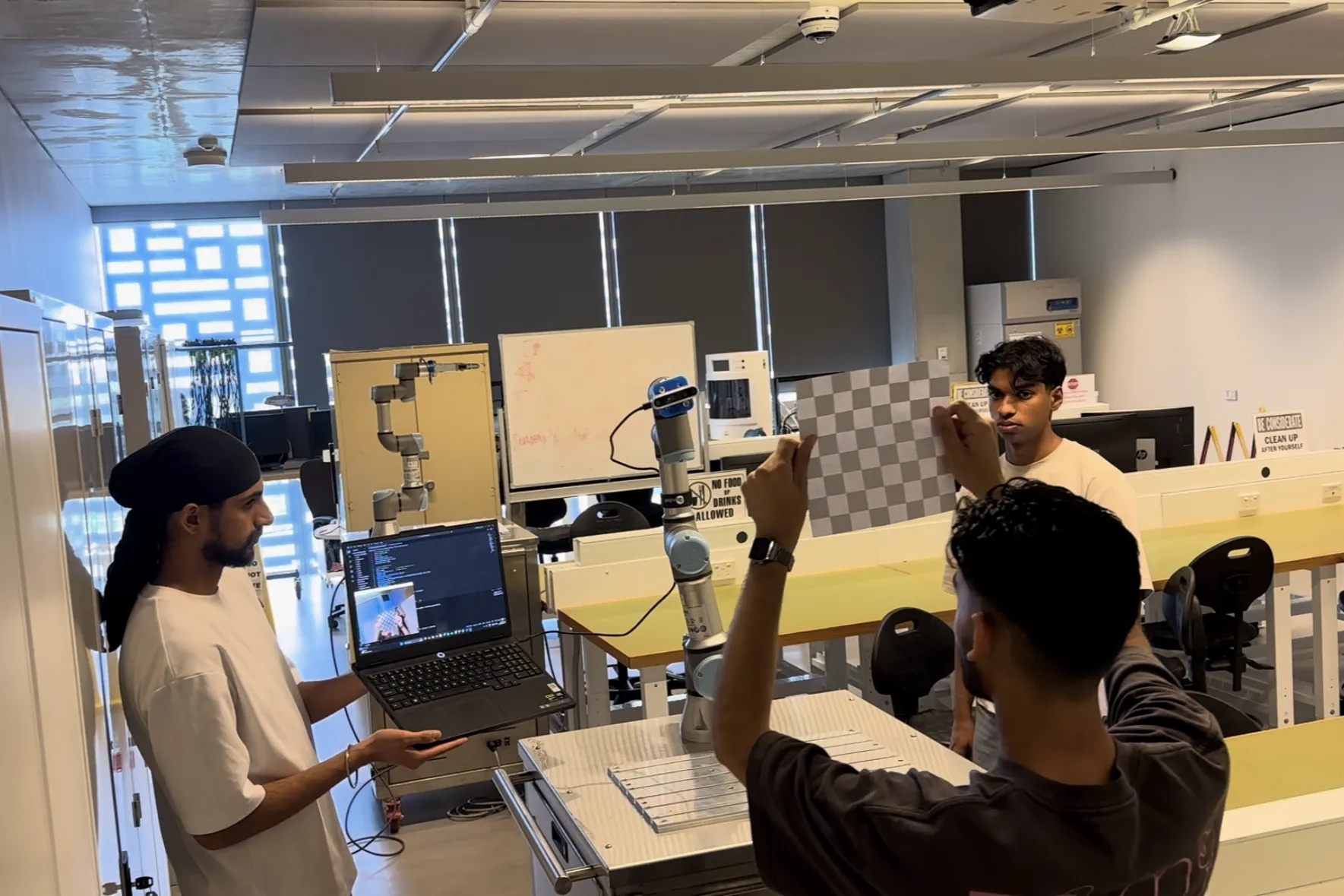
The arm holding onto the board as it is moved by hand. The camera is on the tool, so it moves with the arm, and the controller never works out where the board is in the room. It only ever sees how far the corners have drifted from where they should sit in the image. A simulated UR3 standing in for the real one. The vision process on the left is the real one running against the real camera, and it streams the same six element camera velocity over the same socket it always does. Swapping the arm for a simulation needed no change on the vision side at all, which is what putting one message between the two halves buys you.


1 / 3
The Problem
Sensors and Control for Mechatronic Systems set the brief: make a UR3e arm follow a checkerboard using an Intel RealSense camera mounted on the tool. The board is moved by hand, so the arm has to react continuously rather than execute a path planned in advance.
Image based visual servoing closes the loop in the image itself. Instead of estimating where the target sits in three dimensions and then planning a motion to reach it, the controller works directly on the difference between where the feature points appear and where they should appear. That tolerates calibration error well. A small mistake in the tool to camera transform shows up as a slightly wrong velocity that the next frame corrects, rather than a wrong goal pose the robot drives confidently towards.
My Role
This ran as a team project for the subject, though most of the implementation was mine. I wrote both halves of the running system: the vision process that finds the board and turns it into a camera velocity, and the robot process that converts that velocity into joint motion and streams it to the arm. Tuning the controller gain and the velocity limits until the motion settled was also mine.
Technical Approach
The system runs as two processes that talk over a TCP socket.
The vision process detects a 6 by 5 checkerboard in the RealSense colour stream with OpenCV and takes depth for the target from the aligned depth stream. It compares the detected corner positions against their desired positions in the image, builds the interaction matrix that relates image space motion to camera motion, and solves it for a six element camera velocity. That vector is what goes across the socket, so the vision side never needs to know anything about the robot.
The robot process converts camera velocity into joint velocity. It applies the tool to camera transform to move the velocity into the robot’s frame, then multiplies by the pseudoinverse of the UR3e Jacobian to get joint rates. Those become micro-step joint trajectories published to the arm through rosbridge at 15 to 20 Hz. Controller gain and per joint velocity limits are the two things that decide whether the result is responsive or unstable, and both were tuned by hand against the real arm.
Outcome and What I Would Do Differently
The system worked. The arm tracked the board and held alignment as it was moved around by hand.
Two limitations were clear by the end. The Jacobian solution was not always smooth, and near certain configurations the translation came out jumpy rather than continuous. The usable field of view was also narrower than expected, so the board had to be held close to the camera before detection was reliable, which limited how far the arm could be led.
The change I would make first is the transport. The TCP socket between the two processes exists because the work was done on Windows. Running on Ubuntu and letting ROS carry the messages end to end would remove the custom protocol and the extra hop, leaving one system to reason about instead of two halves joined by a socket. I would also look at damping the Jacobian solution near singular configurations, since that is the most likely cause of the jumpy translation.